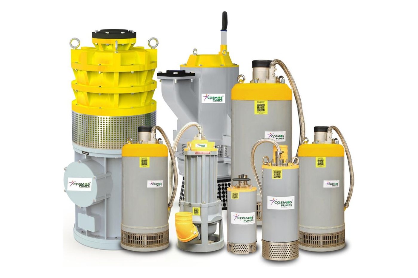
A submersible pump is a centrifugal pump designed to operate fully submerged in the fluid it is pumping. The motor and pump are sealed in a single waterproof unit — eliminating suction lift as a constraint and enabling the pump to push fluid upward through the discharge pipe directly from the source.
For EPC contractors, plant engineers, and procurement teams specifying pumps for construction dewatering, sewage transfer, or slurry handling, understanding the differences between submersible pump types is critical to selecting the correct unit for an application.
Table of Contents
- How a Submersible Pump Works
- Working Principle — Text Diagram
- Key Components
- Types of Submersible Pumps for Industrial Use
- Submersible Pump Selection Guide
- Submersible vs Surface Pumps
- Key Takeaways
- Frequently Asked Questions
How a Submersible Pump Works {#how-it-works}
A submersible pump’s operating principle is the reverse of a surface centrifugal pump. Instead of drawing liquid upward by suction — which is limited by atmospheric pressure to approximately 8–9 metres of lift — a submersible pump pushes fluid from below, using the head developed by the spinning impeller to force liquid up through the discharge pipe.
Here is the sequence of operation:
- Submersion: The pump unit is lowered into the sump, pit, shaft, or water body. The inlet strainer sits near the bottom, close to the water surface being de-watered.
- Fluid entry: Liquid enters through the strainer, which prevents oversize solids from reaching the impeller. Strainer mesh size is matched to the expected solids content of the fluid.
- Impeller rotation: The electric motor drives the impeller at 1,450 RPM (4-pole) or 2,900 RPM (2-pole). Centrifugal force throws liquid radially outward through the volute, generating pressure at the pump outlet.
- Discharge to surface: The pressurised liquid is pushed upward through the discharge pipe to the surface discharge point. A non-return valve prevents backflow when the pump stops.
- Motor cooling: In most industrial submersible pumps, the motor stator is surrounded by and cooled by the pumped fluid. Thermal sensors monitor winding temperature and trip the motor if cooling is compromised.
Why submersible pumps are more efficient than surface pumps in direct-submersion applications: There is no suction energy loss. The pump is already immersed at the fluid level, so all motor power goes into lifting the fluid — not fighting atmospheric pressure limitations at the surface.
The Hydraulic Institute’s pump efficiency standards (ANSI/HI 1.3) confirm that submersible centrifugal pumps achieve higher wire-to-water efficiency in applications where suction lift is unavailable, compared to equivalent surface-mounted pumps drawing from below surface level.
Working Principle — Text Diagram {#working-principle-diagram}
The following diagram describes the flow path in a single-stage submersible dewatering pump:
“ [SURFACE LEVEL] │ │ ← Discharge pipe (fluid under pressure, rising to surface) │ ─────┴───────────────────────────────── [PUMP BODY — submerged below water line] ┌──────────────────────────────────────┐ │ VOLUTE CASING │ │ Fluid exits impeller centrifugally │ │ → kinetic energy converts to │ │ pressure at volute outlet │ │ │ │ [IMPELLER] │ │ Spins at 1,450–2,900 RPM │ │ Creates low pressure at eye (inlet) │ │ → fluid is drawn in and thrown out │ │ │ │ [MOTOR / STATOR-ROTOR ASSEMBLY] │ │ Hermetically sealed against fluid │ │ Cooled by surrounding liquid │ │ Class H insulation (180°C rated) │ │ │ │ [MECHANICAL SEAL] │ │ Prevents fluid entering motor cavity│ └──────────────────────────────────────┘ │ │ ← Inlet strainer (screens solids; mesh matched to fluid type) │ [SUMP / PIT BOTTOM] “
In a multi-stage submersible pump (used for deep dewatering such as tunnel or mine applications), multiple impellers are stacked in series on a single shaft. Each stage adds head pressure — allowing the CDW Ultra High Head series, for example, to achieve shut-off heads of up to 200 M with two impeller stages.
Key Components of a Submersible Pump {#key-components}
| Component | Function | Critical Specification |
|---|---|---|
| Inlet strainer | Screens solids before impeller entry | Mesh size matched to fluid type (4–12mm for CDW, 70mm for CNC) |
| Impeller | Imparts kinetic energy to fluid | Material: hardened SS-410 (HRC 52–55) for abrasion resistance; hi-chrome for slurry |
| Volute / diffuser | Converts velocity to pressure | Sealed against pumped fluid; CI or SS-304 construction |
| Mechanical seal | Prevents fluid entry to motor cavity | TC vs TC (tungsten carbide) for abrasive fluids; SiC vs SiC for slurry |
| Motor stator/rotor | Electric drive for shaft and impeller | Class H insulation (180°C) for continuous duty; Class F for standard sewage duty |
| Power cable | Connects motor to surface control panel | 100% waterproof; H07RNF or PVC; 10–20M factory-supplied length |
| Thermal sensor | Monitors motor winding temperature | Trips motor before insulation failure; critical in unmanned installations |
| Shaft seals and oil chamber | Secondary seal protection between wet-end and motor | Oil-immersed chamber absorbs any seal leakage before it reaches motor |
Types of Submersible Pumps for Industrial Use {#types}
Industrial submersible pumps are not interchangeable. The correct type is determined by the fluid’s solids content, specific gravity (SG), and viscosity. Using the wrong pump type — such as a dewatering pump for slurry duty — results in rapid impeller wear and pump failure within hours.
CDW — Submersible Dewatering Pump
The CDW is the standard industrial dewatering workhorse, designed for dirty and muddy water with suspended solids of 4–12 mm and specific gravity up to 1.1. It is the most widely deployed submersible pump in construction and infrastructure projects across India.
When to specify CDW:
- Foundation and basement dewatering on construction sites
- Highway and metro tunnel dewatering during cut-and-cover operations
- Open-pit mine sumps (where slurry or high-abrasive conditions do not apply)
- Seawater dewatering in coastal construction (SS316 variant with sacrificial zinc anode)
Cosmos CDW — Key Specifications:
- Shut-off head: 15.5 M – 86.5 M (standard); 40 M – 140 M (High Head); 90 M – 200 M (Ultra High Head)
- Flow rate: 450 – 8,500 LPM
- Power range: 1.5 HP – 120 HP (across standard, high-head, and ultra-high-head variants)
- Impeller: Nitride-hardened SS-410 (HRC 52–55) — significantly longer wear life than cast iron
- Insulation: Class H (180°C rated) — withstands overheating events in demanding site conditions
For deep tunnel and mine dewatering applications requiring heads above 86.5M, the CDW High Head (up to 140M) or CDW Ultra High Head (up to 200M) series must be specified — these are 2-stage impeller designs rated for higher operating pressures.
CNC — Non-Clog Submersible Pump
The CNC uses a vortex (recessed) impeller that never contacts the solids in the fluid, making it capable of handling solids up to 70 mm — far beyond what a CDW can pass. This design is standard for sewage bypass and manhole applications.
When to specify CNC:
- Sewage bypass pumping between manholes during sewer rehabilitation
- Manhole cleaning operations (the CNC’s 14-inch diameter makes it a market-leading choice for manhole entry)
- Construction tunnel face drainage where rock cuttings or excavation spoil are present
- ETP/STP emergency bypass where heavy suspended solids are present
Cosmos CNC — Key Specifications:
- Shut-off head: 22 M – 30 M
- Flow rate: 1,250 – 1,500 LPM
- Power range: 6 – 20 HP
- Solids handling: Up to 70 mm (bottom discharge design)
- Construction: SS-304 volute; twin SS mechanical seals; lightweight Al alloy design for manhole deployment
- Cable: 50 sq mm H07RNF (10M) — rated for abusive site conditions
The vortex impeller creates a rotating flow field in the volute that carries solids through without contact with the impeller — eliminating the blockage risk that makes standard impellers unsuitable for large-solids applications.
View Cosmos CNC non-clog pump specifications →
CSW — Sewage Submersible Pump
The CSW is a heavy-duty sewage pump designed for continuous municipal and industrial sewage handling. It passes solids up to 100 mm and handles specific gravity up to 1.7 — suited to dense wastewater in large STP and ETP installations.
When to specify CSW:
- Municipal sewage lift stations and wet wells
- STP/ETP influent pumping and sludge transfer
- Residential and industrial complex sewage collection systems
- Sewage bypass during infrastructure rehabilitation (large-bore bypass with high solids concentration)
Cosmos CSW — Key Specifications:
- Shut-off head: 5 M – 60 M
- Flow rate: 775 – 33,000 LPM
- Power range: 2 – 200 HP
- Solids: 20–100 mm; SG up to 1.7
- Insulation: F-class (155°C) with thermal sensor; optional H-class for high-duty-cycle installations
- Construction: SS316 lifting hook; SS410 high-torsional-strength shaft; dual TC vs TC mechanical seal + oil seal
View the Cosmos CSW sewage pump →
CSL / CSL-TV — Slurry Submersible Pump
The CSL is a heavy-duty slurry pump for the most demanding fluid conditions in industry. It handles fluids with solids content up to 70% by weight and specific gravity up to 2.1 — conditions that would destroy CDW or CNC pumps within hours.
When to specify CSL:
- Ash slurry transfer at thermal power stations (coal ash + water mixtures)
- Harbour construction and channel dredging (silt-dense seawater)
- Coal runoff sump clearance at mines
- Sand and gravel pumping at quarries and wash plants
- Mine waste tailings pumping (high-density slurry containing crushed rock)
Cosmos CSL — Key Specifications:
- Shut-off head: 27.5 M – 52.5 M
- Flow rate: 1,584 – 5,834 LPM
- Power range: Up to 100 HP
- MOC: 27% Hi-Chrome alloy (ASTM A532 Class III) — the industry benchmark for abrasive slurry resistance
- SG: Up to 2.1 (twice the density of water)
The CSL-TV (Twin Volute) variant provides improved hydraulic balance at the impeller, reducing radial load on the shaft and bearings. This is critical in 24/7 continuous duty where radial bearing failure is a primary maintenance cost driver. Twin-volute design can extend bearing service life by 40–60% vs single-volute equivalents under equivalent duty conditions.
View Cosmos CSL slurry pump specifications →
Submersible Pump Range Comparison
| Model | Application | Max Solids | Max SG | HP Range | Head Range |
|---|---|---|---|---|---|
| CDW (Standard) | Dewatering — dirty water | 4–12 mm | 1.1 | 1.5–50 | 15.5–86.5 M |
| CDW High Head | Deep dewatering — tunnels/mines | 4–12 mm | 1.1 | 5–75 | 40–140 M |
| CDW Ultra High Head | Very deep dewatering — mines | 4–12 mm | 1.1 | 50–120 | 90–200 M |
| CNC | Non-clog — sludge bypass/manhole | 70 mm | 1.2 | 6–20 | 22–30 M |
| CSW | Sewage — municipal/STP/ETP | 100 mm | 1.7 | 2–200 | 5–60 M |
| CSL / CSL-TV | Slurry — mine/ash/harbour | 70% by weight | 2.1 | Up to 100 | 27.5–52.5 M |
View the full Cosmos submersible pump range →
Submersible Pump Selection Guide {#selection-guide}
Selecting the correct submersible pump requires four inputs. Specifying in the wrong order — or selecting HP without first establishing head and flow — is the most common cause of pump underperformance and early failure on site.
Step 1 — Identify the Fluid Type
| Fluid Type | Correct Pump | Why |
|---|---|---|
| Clean water / muddy water, SG < 1.1, solids < 12 mm | CDW (dewatering) | Standard impeller handles light-to-moderate solids; efficient for clean dewatering duty |
| Thick sludge, viscous mix, solids up to 70 mm, SG < 1.2 | CNC (non-clog) | Vortex impeller passes large solids without contact or blockage |
| Sewage / STP wastewater, solids up to 100 mm, SG up to 1.7 | CSW (sewage) | Rated for high solids density and larger-diameter fibrous solids |
| Heavy slurry, solids > 70% by weight, SG up to 2.1 | CSL (slurry) | 27% hi-chrome MOC required to withstand abrasive wear at this concentration |
Step 2 — Determine Required Total Head
Total head (TH) = Static head + Friction losses in discharge pipe
- Static head: Vertical rise from the pump discharge to the point where fluid is discharged to atmosphere or into a discharge tank.
- Friction losses: Calculated from pipe diameter, length, and flow velocity. For correctly sized dewatering hose, add 10–15% of total pipe length as friction allowance. For runs exceeding 100 M, increase this to 20%.
- Velocity head: Negligible for standard dewatering applications — ignore unless pipe velocity exceeds 3 m/s.
Rule of thumb: Add 15% safety margin above calculated TH to ensure the pump operates within the stable range of its performance curve.
For underground mine and deep tunnel applications where static head may reach 80 M–200 M, the CDW High Head or CDW Ultra High Head series must be selected. The standard CDW series is not rated for these pressures.
Step 3 — Calculate Required Flow Rate
Required flow rate is determined by:
- Peak inflow rate: How quickly water enters the excavation during peak rainfall or highest groundwater pressure. This must be measured or calculated from the hydrogeological report for the site.
- Drawdown volume: Total volume to be removed in the required drawdown time.
For construction dewatering, IS 9187 (Code of Practice for Ground Dewatering) recommends designing pump capacity at 2.5–3× the measured steady-state inflow rate to maintain a drawdown safety margin against storm events.
Step 4 — Select HP from Performance Curves
Once fluid type, required TH, and required flow rate are known, HP is determined from the manufacturer’s pump curves — it is the output of the selection process, not an input. Selecting by HP first (e.g. “I need a 20 HP pump”) without first establishing the head-flow requirement leads to misapplication.
Additional selection factors:
- Impeller MOC: For abrasive fluids — grit, rock flour, sand — verify impeller hardness. CDW uses SS-410 impellers (HRC 52–55); CSL uses 27% hi-chrome. Cast iron or mild steel impellers will wear rapidly in abrasive duty.
- Duty cycle: For 24/7 continuous duty, specify Class H insulation and ensure the motor HP is at the duty point — not at the pump’s maximum flow (which overloads the motor).
- Installation depth: Verify that the factory-supplied cable length (15 M for CDW; 20 M for CDW Ultra High Head) is adequate for the planned depth, or specify cable extension.
Submersible vs Surface Pumps: Which to Choose {#submersible-vs-surface}
| Choose Submersible (CDW/CNC/CSW/CSL) When | Choose Surface Auto-Prime (CAP) When |
|---|---|
| No suction head available — pump must be immersed in fluid | Suction head available at surface (up to 8.5 M) |
| Electric power supply is available and reliable at the pump location | Engine-driven preferred due to no/intermittent grid power |
| Pumping sewage, sludge, or slurry from a closed sump or wet well | High portability required — pump needs to move between multiple sites |
| Multiple small sumps in close proximity (one pump per sump) | Very high flow rates required (>74,000 LPM achievable with large CAP) |
| Space constraints prevent surface-mounted pump installation | Remote locations with no power infrastructure (CAP runs on KOEL, Eicher, Baudouin, CAT engines) |
Key Takeaways {#key-takeaways}
- A submersible pump operates fully immersed in fluid, pushing liquid upward through the discharge pipe. There is no suction lift constraint, making them the only viable option when a pump must be immersed.
- The four main industrial submersible types are CDW (dewatering), CNC (non-clog/sludge), CSW (sewage), and CSL (slurry). Fluid type — specifically solids size, specific gravity, and abrasiveness — determines which series is correct.
- Pump selection requires establishing fluid type, required head, and required flow rate before determining HP. Specifying HP first leads to misapplication.
- For abrasive fluids, impeller material of construction is as important as the hydraulic specification. Standard impellers fail rapidly in slurry duty; 27% hi-chrome is the minimum for CSL applications.
- Submersible pumps are the correct choice when no suction head exists, when the fluid must be pumped from a submerged point, or when sewage or slurry characteristics require an immersion-rated design.
Frequently Asked Questions {#faq}
What is a submersible pump?
A submersible pump is a sealed centrifugal pump designed to operate fully submerged in the liquid it is pumping. The electric motor and pump assembly are enclosed in a single waterproof unit. Unlike surface centrifugal pumps, which draw liquid upward by suction, submersible pumps push fluid upward from below — eliminating the suction lift limitation of approximately 8–9 metres that restricts surface pump applications.
What is the difference between a dewatering pump and a submersible pump?
A dewatering pump is a specific category of submersible pump — designed for removing dirty, muddy, or grit-laden water from construction sites, mines, and tunnels. All dewatering pumps are submersible, but not all submersible pumps are dewatering pumps. Submersible pumps also include sewage pumps (CSW), slurry pumps (CSL), and non-clog pumps (CNC), each engineered for different fluid types and solids concentrations.
What are the main types of submersible pumps used in construction and industry?
The four main industrial types are: (1) CDW — Dewatering pumps for muddy water with solids up to 12mm; (2) CNC — Non-clog pumps for thick sludge and solids up to 70mm; (3) CSW — Sewage pumps for municipal wastewater with solids up to 100mm and SG up to 1.7; and (4) CSL — Slurry pumps for high-density slurry with solids up to 70% by weight and SG up to 2.1. Each is rated for a different fluid density and abrasion level.
How does a submersible pump work?
A submersible pump works by spinning an impeller submerged in the liquid. The rotating impeller creates centrifugal force that throws liquid outward, generating positive pressure at the pump outlet. This pressure pushes the liquid upward through the discharge pipe to the surface. Since the pump is immersed at the fluid level, there is no suction energy loss — all motor power goes into lifting the fluid. The motor is cooled by the surrounding fluid and protected by hermetic seals.
How do I select the right submersible pump?
Begin with the fluid type (clean water, muddy water, sewage, or slurry). Then determine: (1) total head required — static head plus pipe friction losses; (2) required flow rate — calculated from site inflow rate and target drawdown time. Use these two values against the pump’s published performance curves to identify the correct model and corresponding motor HP. For abrasive applications, also verify impeller MOC (material of construction) — hardened stainless steel for dewatering, hi-chrome for slurry.
Can a submersible pump run dry?
No. Standard submersible pumps must not run dry. The pumped fluid cools the motor stator and lubricates the mechanical seals. Running without fluid overheats the motor winding and destroys the mechanical seal within minutes, causing permanent damage. To protect against dry running in sumps that may empty, always install a dry-run protection float switch or use a pump fitted with a thermal sensor wired to an automatic cut-off relay.
What is the difference between a CDW dewatering pump and a CSL slurry pump?
The CDW is designed for dirty water with suspended solids of 4–12mm and specific gravity up to 1.1. Its impeller is nitride-hardened SS-410 steel (HRC 52–55). The CSL is designed for dense slurry with solids up to 70% by weight and SG up to 2.1. Its wetted parts are 27% hi-chrome alloy (ASTM A532 Class III), which resists abrasive wear at high solids concentrations. Deploying a CDW in CSL duty results in impeller wear failure typically within 24–48 hours of operation in high-abrasive slurry.
What is the maximum depth a submersible pump can operate at?
It depends on the motor design, cable rating, and pump series. Standard Cosmos CDW pumps are supplied with a 15M waterproof power cable. The CDW Ultra High Head series — designed for deep tunnel and mine dewatering up to 200M shut-off head — is supplied with a 20M cable. For installations deeper than the factory cable length, cable extension kits are available; the cable cross-section must be verified for voltage drop over the full run length to prevent motor underperformance or overheating.
About Cosmos Pumps
Cosmos Pumps Pvt. Ltd. manufactures ISO and CE-certified industrial submersible pumps at its 25,000 sq. ft. facility in Faridabad, India. The Cosmos submersible range — CDW (dewatering), CNC (non-clog), CSW (sewage), and CSL/CSL-TV (slurry) — covers the complete spectrum of industrial pumping requirements for EPC contractors, mining operators, plant engineers, and municipal infrastructure teams.
For pump selection assistance, technical data sheets, or a project quotation:
- Explore the full Cosmos submersible pump range →
- Contact us: cosmos@cosmospumps.com | +91 99333 22238
This article is written for EPC contractors, plant engineers, and procurement teams specifying industrial submersible pumps for dewatering, sewage, and slurry applications in construction, mining, power, and municipal infrastructure projects.